

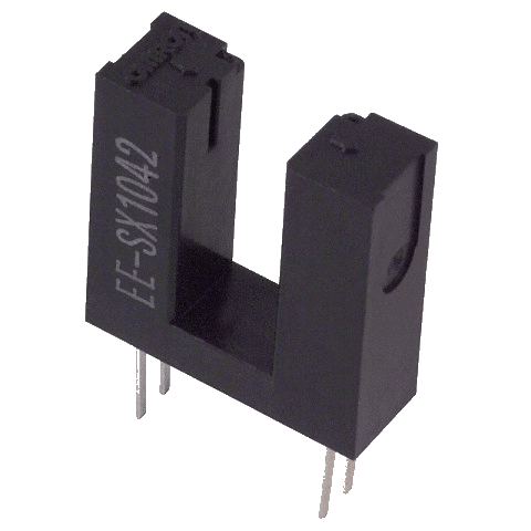
Time for another update, and this time, I thought that I will share with you, my homemade speedometer. Using a photo-diode, a LED, a BC547-transistor, and a few resistors.
So, the idea behind this is that I wanted a way to read the velocity off of an axle, using discs. And I wanted a DIY-solution, and I remembered reading about fork couplers.
And I didn’t want to wait for the part to arrive, noir did I order any (small electronics like this can be expensive as shit when you order within Sweden, the part is much cheaper if I would order it from China, but I would have to wait for 3-6 weeks).
So I decided to build my own.
Transistor as a switch.
So I began prototyping, and I quickly layed out what I wanted the data from the circuit to look like. The most benefitial for me is a square-wave, in a close resemblence to a PWM-wave. And in order for my circuit to produce this wave, I decided to use a BC547-transistor. (NPN).
So, suddenly a schematic appears!
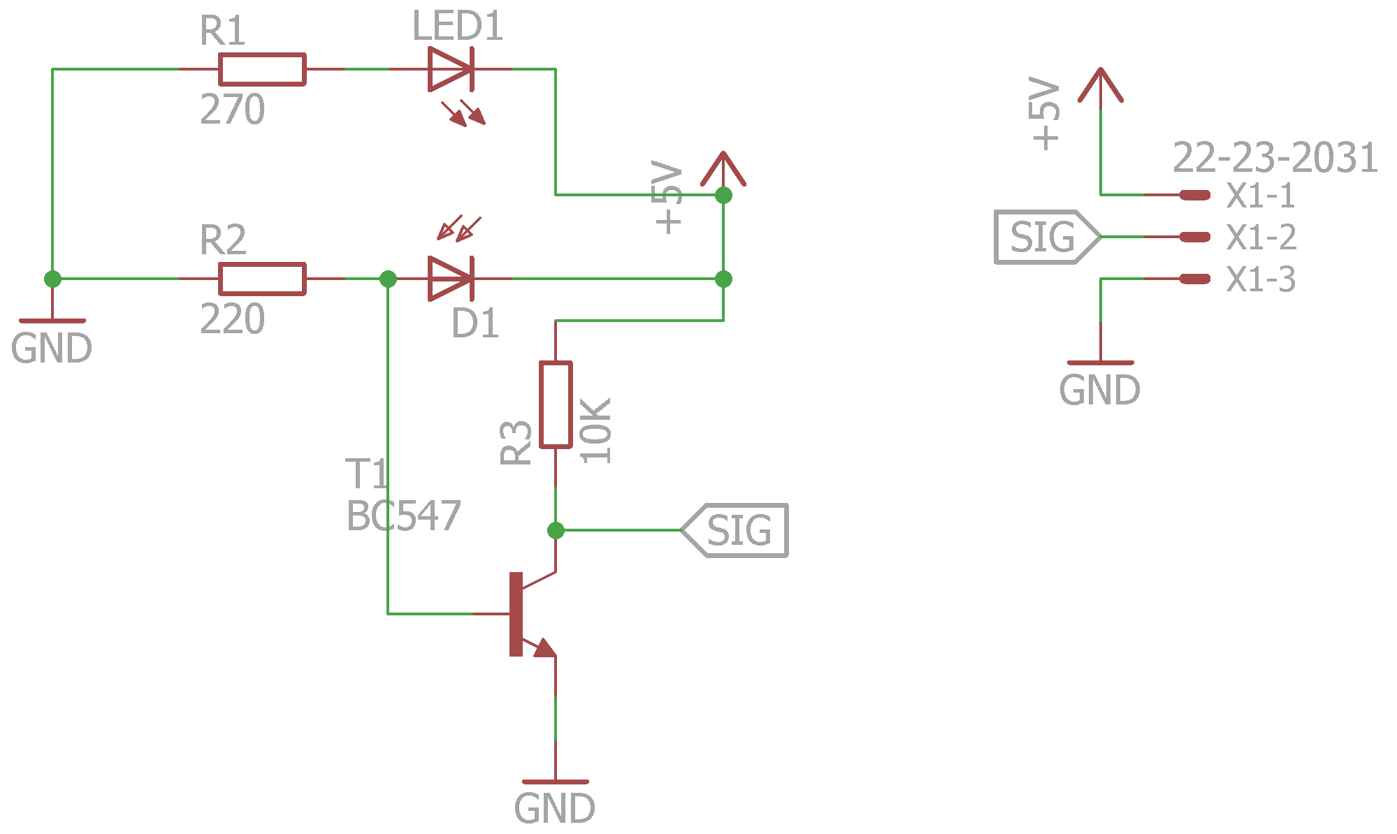
Schematic for DIY-speedometer
The LED1 and R1 is self-explanatory. And between R2 and D1, I got a reading of 0.2V when the diode was covered, and a reading of 0.7V when it was uncovered, and exposed too the LED.
And in order a BC547 to begin conducting electricity, a Vbe-voltage higher or equal to 0.7V is required.
Thus the transistor creates a rising edge when the photo-diode is uncovered, and a falling edge when it’s covered.
Just make sure that you know what wave-lengths of the LED to use, in my case, anything but green LEDS worked.
I am bored.
Glad you said so, here’s the board.
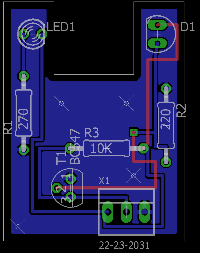
The DIY-speedometer-board.
The gap between the LED and the diode is roughly 1x1cm.
The connector at the bottom is rather straight forward, it’s a molex 3 pin, with the pin-assignment like this (From the left to the right):
1 – Voltage
2 – Signal
3 – GND
For questions, drop them in the comment-field.
–Rickard.

Reblogged this on Electronics Infoline.